|
From East To West |
|
Solar Collect Limited © 2014 Registered in England and Wales, Company no. 6234018 Preston, PR2 8WB. |

|
Soft Start Power Inverters 24 v /12 v DC to 230 volt AC 600 W / 300 W Maximum Continuous Output Power
These devices are designed to produce mains power (230 V, AC) from a low voltage DC power source, i.e. a 24 v or 12 V battery. They are supplied with 60 cm battery leads for temporary connection using crocodile clips. (The 300 W also has a cigar lighter adaptor for in-car use.) The Inverters will provide up to 600 W /300 W continuous Power and up to 1000 W /600 W surge Power via a British Standard Socket BS1363. The AC output is in the form of a 3-level modified sine wave with THD ≈ 25%. Output regulation is achieved by using pulse width modulation (PWM), maintaining the output power to be equivalent to that of 230 V rms sine wave, within ± 5%. The Output Frequency is maintained at 50 Hz ± 0.4% by an internal stable R-C oscillator. Soft start circuitry is included to enable the device to cope with switch on current surges, for example with inductive or capacitive loads. These inverters also incorporates micro-controller protection against: input over-voltage/ under- voltage, output overload/short circuit. They are cooled by a micro–controlled cooling fan which operates progressively as the power increases. The controller will automatically shut down the inverter at 65 °C and only re-start it again when the temperature has fallen to below 50°C. An audible alarm sounds to indicate overload, over-temperature or low input voltage. The input is reverse polarity protected by a 35 A fuse in the DC positive input. The blade type fuse holder is available externally at the rear of the instrument for the 300 W type, and internally for the 600 W version. This Inverters are Class I devices, housed in a metal case with an external protective Earth terminal. They are internally bonded for safety, DC Negative to Case to AC Earth Socket. We recommend that they be used with an external earth connection.
For additional protection against cable faults or moisture ingress, they should be used with a Type “A” portable residual current circuit breaker (commonly known as an RCCB or RCD).
These devices are ideal to power a caravan or small house low energy lighting system, or low current appliances such as a TV, Radio or Laptop Computer. IMPORTANT SAFETY NOTE FOR SOLAR COLLECT INVERTERS THESE INVERTERS ARE DESIGNED FOR INDEPENDENT USE ONLY. THEY SHOULD NOT NORMALLY BE CONNECTED TO DOMESTIC HOUSEHOLD WIRING, WHETHER OR NOT THE BUILDING IS GRID CONNECTED AT THE TIME. FOR SUCH PURPOSES A GRID–TIE INVERTER IS USUALLY EMPLOYED. SHOULD THE INVERTER BE USED AS PART OF A PERMANENT INSTALLATION, SUCH AS A STANDBY SUPPLY POWERED BY A SEPARATELY CHARGED BATTERY, THEN THE OUTPUT MUST BE PRESENTED ON AN INDEPENDENT SOCKET. A FREE LEAD WITH A PLUG MUST BE CONNECTED TO THE CIRCUIT OR EQUIPMENT TO BE POWERED. THE CHANGE OVER FROM THE MAINS OR GENERATOR TO THE INVERTER MUST BE ACCOMPLISHED BY SWAPPING THE PLUG OVER FROM THE MAINS TO INVERTER MANUALLY. IF POWERED FROM A VEHICLE BATTERY, THEY CAN BE USED WITH NEGATIVELY EARTHED VEHICLES / SYSTEMS ONLY. Specifications
Maximum Continuous Output Power 300W
Maximum Surge Output Power 600W
Input Voltage 12 V (10–15 V) DC
Output Voltage 230 V ± 5 %
Output Frequency 50 Hz ± 0.4 %
Efficiency > 90 %
Quiescent Input Current < 0.2 A
Output Waveform 3 level MSW
Safety Compliance:
EN 60950: 2000 Electrical Safety
EN 61000-6: 2007 Electromagnetic Compatibility
Protection Systems: Microprocessor Controlled
Alarms: Audible and Visual
External Switch: On / Off at front
Ambient Operating Temperature - 20 °C to 40°C |
|
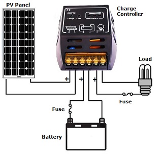
The CMP12, 12/24 V auto switch Charge Controller permits load currents of up to 12 A. It is of the “2 level” type with a number of integral protective functions. The Charge LED is illuminated continuously while the battery is charging. It is intermittent in the float state. The full charge default is 13.8 v at 25°C and is temperature compensated at -18 mv/°C for a 12 v battery. The red LEDs indicate the battery level. They illuminate, from left to right when the battery voltage exceeds 10.0 v, 11.9 v, and 13.8 v respectively. The green LED illuminates when the load output is on. The controller disconnects the load when the battery voltage falls below 10.9 v, and reconnects the load when the battery voltage exceeds 12.6 v. The load is shown represented by a lamp. But it could be anything with the appropriate power consumption. For example, with a 12 volt system, a low power inverter with a continuous load of up to 150 W. (This corresponds to a load current of about 12 A.) PLEASE NOTE: If the load is earthed, for example the negative input of an inverter, do not try to earth any other point on the circuit. The negative terminals are not common on this type of controller. If you are listening to an AM radio broadcast with a very weak signal, then the automatic switching of the controller has been known to cause a slight amount of audible interference. This can easily be fixed by a metallic screen around the controller. Nothing high tech is required. A biscuit tin or similar will do just fine! If the average daily discharge in Ah exceeds the average daily charge in Ah from the PV panel, the battery will gradually be discharged and tend to “Sulphate”. To prevent permanent damage to the battery a periodic booster charge will be necessary. |
|
Electrical Specifications Model CMP-20A Rated Voltage 12V/24V auto switch Load Current Max ≤ 20A Full charge cut-out 13.7 / 27.4 volts (Defaults) Low voltage cut-out 10.5~11.0 / 21.0 ~ 22.0 volts (Defaults) Temperature compensation -3mv/℃/cell Quiescent Current ≤ 30 mA Battery - Output voltage drop < 240 mv Dimensions / cm 15.0 x 12.3 x 5.5 Gross Mass 420 g Please Note: The default full charge point of 13.7 v is the optimum for our Gel batteries. However it can be adjusted via the menu from below 12 v to above 14.5 v. Likewise the load disconnect default of 10.5 v can be adjusted from 10 v to 12 v. Also the load reconnect default of 12.6 v can be adjusted from 11 v to above 14v. |