|
From East To West |
|
Solar Collect Limited © 2014 Registered in England and Wales, Company no. 6234018 Preston, PR2 8WB. |

|
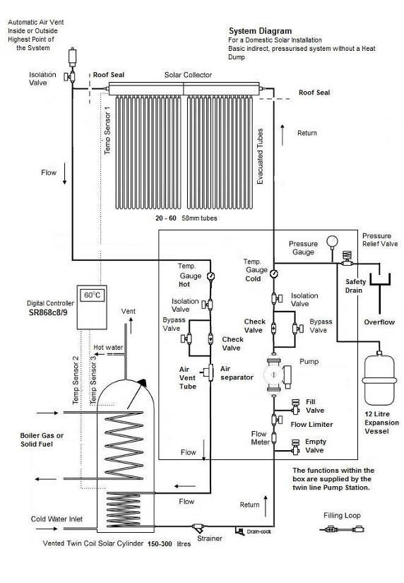
Notes on Solar Hot Water System Components (Indirect, Pressurised System without a Heat Dump) Solar Collector (Solar Keymarked for MCS approval) This consists of evacuated tubes with a horizontal header (manifold) at the top. With heat pipe types, the tubes should be inclined at 30 – 60 ° to the horizontal and face ESE to WSW. (Due south at 40 ° is best.) Vertical tubes on a south facing wall will work, but with only 50 % output.
Solar Cylinder (It will almost certainly already have MCS approval.) This is usually twin coil with thicker insulation (50 mm) and so it retains heat longer. It has a volume to match maximum heat from the collector in one sunny summer day. Rule of thumb: 20 tubes → 150 – 210 l 40 tubes → 210 - 250 l 60 tubes → 250 – 300 l
Digital Controller This switches on the pump when T1 – T2 exceeds pre-set amount (default 8 ℃). It switches off the pump when T1 – T2 ≤ 4 ℃. It also contains several other control functions and protective functions to prevent freezing or overheating.
Automatic Air Vent It is only used when commissioning or maintaining the system. This releases trapped air but not liquid. It must be mounted in a pipe turn and vertical at the highest point (inside or outside roof). (Inside is usually more convenient.) Fitted with an isolation valve that is normally closed.
Air Separator Continually separates out dissolved air which is periodically vented through a small valve.
Pressure Relief Valve This is a mandatory safety requirement. It is usually set for 6 bar maximum and it can also be operated manually. Useful also as a manual air vent when filling. For MCS approval a suitable safe drain-away for very hot liquid must be provided.
Filling Loop If flushing with the mains, Water Supply Regulations require the use of a filling loop, with double check and isolation valves, to prevent any possibility of contaminating the supply. They are widely available and inexpensive.
Fill Valve This is used when commissioning, to flush the system and subsequently fill with Heat Transfer Fluid (Solar Antifreeze). A pressure pump such as a garden pressure spray can be attached to pressurise the system.
Empty Valve This is used open when filling or flushing the system. All valves are of the modern “ball” type, usually lever operated.
Flow Meter This indicates the flow rate, which is set to a suitable level that depends on the number of tubes in the collector.
Flow Limiter This contains a screwdriver operated ball valve to set the correct working flow rate.It is usually initially closed when filling the system. (To direct the fluid up and through the manifold). Then used fully open to pressurise the system and subsequently circulate the fluid to allow air to be driven out. Rule of thumb: 20 tubes → 2 - 3 l/min, 40 tubes → 4 – 6 l/min, 60 tubes → 6 -12 l/min.
Check Valves (Non-return Valves) These are essential to prevent reverse circulation by convection when the pump is off. By-pass Valves These are used when flushing, or filling and pressurising the system. Isolation Valves Are used to separate the collector from the rest of the system for maintenance or repair.
All of the above 3 types of valves are contained within the multifunction ball valves that are integrated into the Thermometer housings in the Flow and Return lines.
Circulating Pump This is switched on and off by the Digital Controller. Supplied with the Twin line Pump station is a Grundfos Solar, Low Energy Pump as required for MCS approval. This has three speed settings, of which only the lowest is normally required for most domestic installations.
Pressure Gauge The minimum pressure is usually calculated as 0.5 bar + 0.5 bar for each 5m rise to the collectors, i.e. about 1 bar. An operating pressure of 1-2 bar is normally set when filling cold with heat transfer fluid. This will rise slightly when hot. Rapid fluctuations in pressure indicate air in the system.
Expansion Vessel This helps to maintain a constant pressure as the fluid expands. It contains a bladder that expands against a pressurised gas volume. It is pre-charged to 2.5 bar and thus the pressure can rise to this level before the regulating effect starts. It is connected to the Pump Station via a length of uninsulated flexible stainless steel tubing through a special adaptor containing a separating double check valve. Thus the vessel can be replaced without having to depressurise the circuit.
Line Strainer This is important to preserve the life of the pump as it captures circulating debris in the solar circuit. It is best at the coolest point where the return exits the cylinder. It may double as a drain, but it is useful to fit a drain cock also. Heat transfer Fluid This contains special solar antifreeze and a corrosion inhibitor. It can be used up to 50% concentration but 25 -30 % is often ok in the UK. (Dilute only with deionised water.) The controller also has a frost protection function which circulates the fluid below 4 ℃.
Pipework For up to 5 Collectors in series (100 tubes) should be 15 mm Cu or DN16 Flexible Stainless Steel. Use 19 mm high temperature insulation in cold spaces.
Roof Seals For pipes and sensor cable, effective seals are required for MCS approval. Solardek™ lead and silicone rubber roof flashings are provided with the kit. |
|
Plumbing Schematic See Below |